H / Double H / Square / Rectangular Finned Tube for Economizer Product Introduction
I. Concept
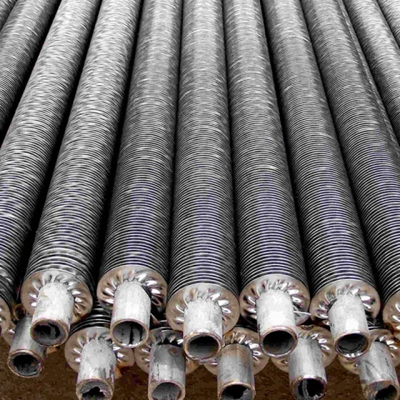
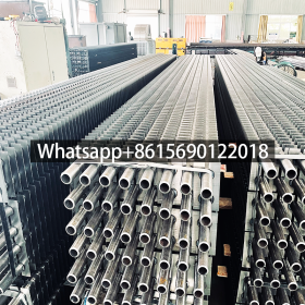
The H finned tube is a high-efficiency heat exchange component. Its core structure consists of a smooth base tube and symmetrically welded rectangular fins on both sides, forming an “H” shape in cross-section (see Figure 1). By welding two steel plates with central arcs to the base tube, it extends the heating surface, significantly increasing the heat transfer area and optimizing fluid dynamics.
H / Double H / Square Fin Tube for Economizer
أنبوب الزعانف—-Square fin tube, H fin tube, rectangular fin tubes, double H fin tubes
H fin tube known as square fin tube, There are two type of H fin tubes, one type with single tube, normal called square fin tube, the other with Double tube, normal called rectangular fin tubes. and also manufactured as per customers requirements. Due to rectangular shapes, which can offer large surface area compared to the Spiral Finned tubes. Due to larger surface area available, these finned tubes are used mostly in Air Heating application to reduce the overall size of the equipment.
H fin tube is a kind of boiler parts, to have two steel circular symmetry to be welded on fluorescent tubes to form fins positive shap much like letter “H”, so called H-fin tube. H-economizer widely used in utility boilers, industrial boilers, marine power, such as the tail of heat exchanger components.
Principle:
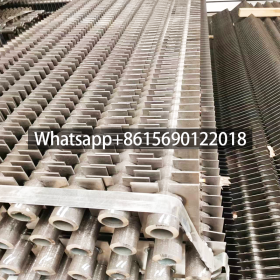
H-economizer two rectangular fin, similar to a square, its edge length for the fluorescent tubes of 2-fold, an expansion of the heating surface.
H-economizer flash resistance welding processes used, the welding seam after the high rate of fusion, weld tensile strength, and has good thermal conductivity. H-economizer can also manufacture dual tube “double H” type fin tubes, its rigid structure, and can be applied to a longer tube row occasion.
Max. Working Temperature: 300 °C
Atmospheric Corrorsion Resisitance: OK
Mechanical Resistance: Good
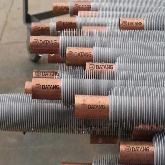
Fin Material: Copper, Aluminum, carbon steel, stainless steel
Base Tube materials: Any material available, such as Carbon steel Tube, A179, A192, A210, stainless tube A269/A213 T5 T11 T22 304 316
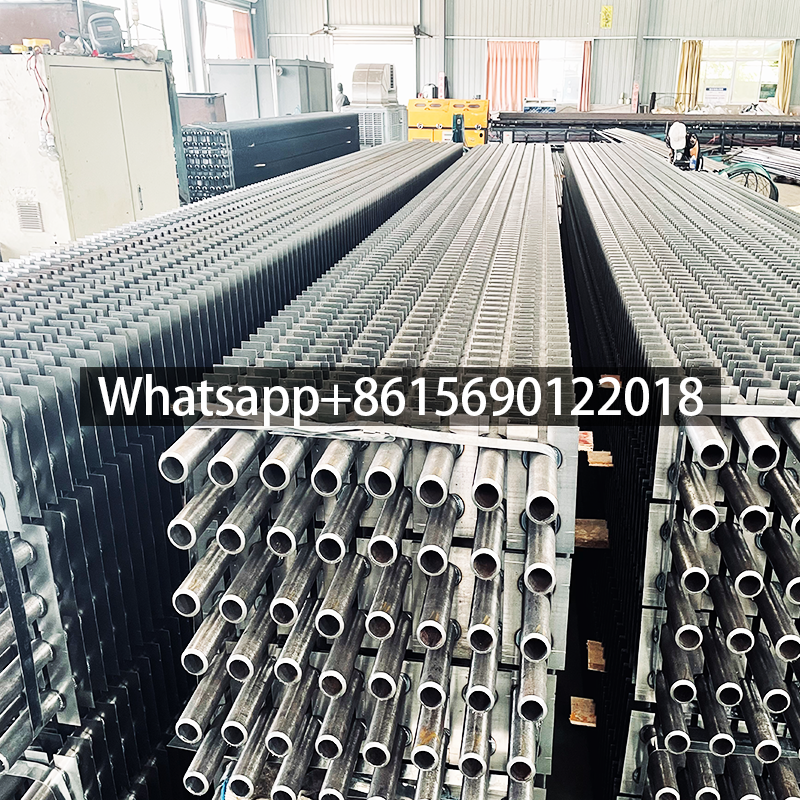
Rectangular Finned Tubes
Single pipe square finned tubes and twin pipe rectangular finned tubes are also manufactured as per customers’ requirements. These are particularly suitable for dust laden exhaust gases, e.g. for economizers in coal and oil fired units or waste incinerators.
II. H type Finned Tube Working Principle
The H-finned tube achieves superior heat transfer through its unique structural design and thermal mechanisms:
1. Structural Features & Heat Conduction Path
- Dual Fin-Base Composite Structure:
Two parallel rectangular fins are symmetrically fixed to the base tube via high-frequency welding, creating an “H” cross-section. This increases the heat transfer area by 6–10× compared to bare tubes. The welded interface ensures rapid heat conduction. - 3D Extended Heat Transfer Surface:
Multi-layer micro-channels on the fins enhance gas-solid coupled heat transfer while reducing localized thermal loads.
2. Convection Heat Transfer Enhancement
- Turbulent Flow & Boundary Layer Disruption:
Vortices generated at fin edges break fluid boundary layers, reducing thermal resistance and boosting heat transfer coefficients by 30–50%. - Flue Gas Corridor Effect:
Narrow channels between fins accelerate gas flow (>8 m/s), enhancing convection and minimizing ash deposition.
3. Anti-Fouling & Self-Cleaning Properties
- Structural Anti-Clogging Design:
Welded ridges between fins block large ash particles. - Vibration-Driven Ash Removal:
Micro-vibrations (5–20 Hz) under pulsating airflow dislodge ash deposits, enabling continuous operation.
4. Material Compatibility & Thermal Stability
- Bimetal Composite Process:
Base tubes (e.g., carbon steel) and fins (e.g., Corten steel) are metallurgically bonded for strength and corrosion resistance. - Thermal Expansion Compensation:
Symmetric fin layout neutralizes thermal stress, ensuring stability at ≤600°C.
Principle Schematic
High-temperature gas → Flows over fins → Heat conducts to base tube → Working fluid (water/steam) absorbs heat ↑ Turbulence ↑ Welded contact points ↑ Fluid circulation removes heatIII. Rectangular Finned Tube Structure & Manufacturing
Key Features
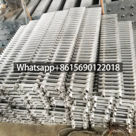
- Rectangular/square fins (typically 2× base tube diameter in length).
- “Double H” variants enhance rigidity for long-tube applications.
- Narrow “flue gas corridors” guide airflow and minimize ash accumulation.
Manufacturing
- Laser/conventional welding ensures robust fin-to-tube bonding.
- In-line arrangement reduces flow resistance and improves efficiency.
IV. Square Finned Tube Applications
- Power Plants:
- Boiler economizers, air preheaters, waste heat recovery.
- Example: Nickel-alloy laser-welded H-finned tubes improve heat transfer by 40% in coal-fired plants.
- Industrial Boilers:
- Replaces bare tubes in high-temperature (>300°C) economizers.
- Petrochemicals:
- Refineries, ethylene crackers, LNG systems. Bi-helical fins reduce pressure drop by 28% and resist sulfur corrosion.
- Environmental Engineering:
- Flue gas desulfurization (FGD), waste incineration. 316L/Ti composite tubes withstand pH 1–2 environments.
- HVAC Systems:
- Low-temperature radiators for large spaces with minimal corrosion/flow loss.
V. H type Finned Tube for Economizer Advantages
- High Efficiency:
- 3–5× larger heat transfer area vs. bare tubes; optimized airflow reduces resistance.
- Anti-Fouling:
- Self-cleaning design ideal for high-ash fuels (e.g., biomass).
- Durability:
- Double-H structure withstands high pressure/vibration; materials last >10 اعوام.
- Cost-Effectiveness:
- Reduces fan power consumption and energy waste (≥90% thermal utilization).
- Versatility:
- Compatible with steam, hot water, thermal oils; customizable materials for extreme conditions.
VI. H type Finned Tube for Economizer Specifications
Key Parameters
| Category | Specifications | Examples/Notes |
|---|---|---|
| Base Tube | ||
| Diameter | Φ25–Φ51 mm (standard), up to Φ100 mm | Φ32×4 mm, Φ51×6 mm |
| Wall Thickness | 2.0–6.0 mm (standard) | Thick-walled (≥4 mm) for high pressure |
| Fins | ||
| Height | 10–50 mm (standard), up to 60 mm | 1:1–2:1 height-to-diameter ratio |
| Thickness | 0.5–4.0 mm | 0.8–1.5 mm for high-frequency welding |
| Spacing | 2–30 mm | Narrow spacing (2–6 mm) maximizes area |
| Type | Single-H, Double-H | Double-H for rigidity in long spans |
| Materials | ||
| Base Tube | Carbon steel (20#, Q235), ND steel, stainless | ND/stainless for corrosive environments |
| Fins | Same as base or galvanized steel | Aluminum for lightweight systems |
| Performance | ||
| Temperature Range | ≤600°C (carbon steel), ≤900°C (alloys) | ND steel for high-temperature waste heat |
| Pressure Tolerance | 0.5–4.0 MPa | Alloy tubes for high-pressure systems |
Selection Guidelines
- High-Erosion Environments (e.g., coal boilers):
Φ51×6 mm carbon steel + Double-H fins (spacing ≥10 mm) reduces erosion to 43% of bare tubes. - Waste Heat Recovery:
Stainless steel (316L/ND) + ≥25 mm fins; in-line arrangement. - Lightweight HVAC:
Φ25×2 mm aluminum tubes + 0.8 mm fins (30–50% lighter but lower pressure tolerance).
Note: Final design requires validation based on gas composition, temperature, and spatial constraints.