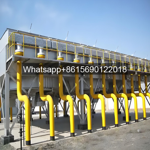

What is a Fin Fan Cooler?
A fin fan cooler uses ambient air as a cooling medium, passing across the outside of finned tubes to cool or condense the high-temperature process fluid within. This device is often referred to as an “air cooler” oder “air-cooled heat exchanger.”
Air Cooler Features and Applications
An air cooler consists of a finned tube bundle, fan, louvers, frame, maintenance platform, and other components as required by the user.
When the air cooler is in operation, the material being cooled flows through the tubes, while ambient air, driven by the fan, flows through the tubes. The temperature difference between the two is used to cool the material. Using an air cooler instead of a water cooler for cooling or condensing the medium not only saves precious water resources but also reduces water pollution. It also offers low maintenance costs, safe and reliable operation, and a long service life. Especially in northern and western my country, air coolers offer significant cost and environmental advantages over other heat exchange equipment. Air coolers are widely used in the petrochemical, chemical, pharmaceutical, coal, power, and metallurgical industries.
Air Cooler Structures
● Induced Draft Fin Fan Cooler
The finned tube bundle is located below the fan and duct. Because the duct protects the finned tube bundle from dust, rain, snow, and direct sunlight, an induced draft air cooler offers relatively stable heat exchange performance. It also offers advantages such as uniform air volume distribution, reduced heat cycling, low noise, and long service life.
● Forced Draft Fin Fan Cooler
The finned tube bundle is located above the fan and duct, with the fan motor located at the bottom of the air cooler, making maintenance very convenient. Furthermore, the fan motor’s ambient temperature is relatively low, significantly extending its service life.
● Inclined Fin Fan Cooler
The finned tube bundle is tilted 60° at the top of the frame, occupying a relatively small footprint and making it suitable for condensing materials. Its internal tube resistance drop and heat transfer coefficient are superior to those of horizontal air coolers.
● Combined Fin Fan Cooler
The finned tube bundle (stage 1) is tilted 60° at the top of the frame, occupying a relatively small footprint. The finned tube bundle (stage 2) is located on both sides of the fan inlet, and a humidification water spray system is installed on the windward side of the finned tube bundle (stage 2). In extremely high ambient temperature conditions, the humidification water spray system significantly improves the heat removal capacity of the equipment, allowing the air cooler to easily survive the summer.
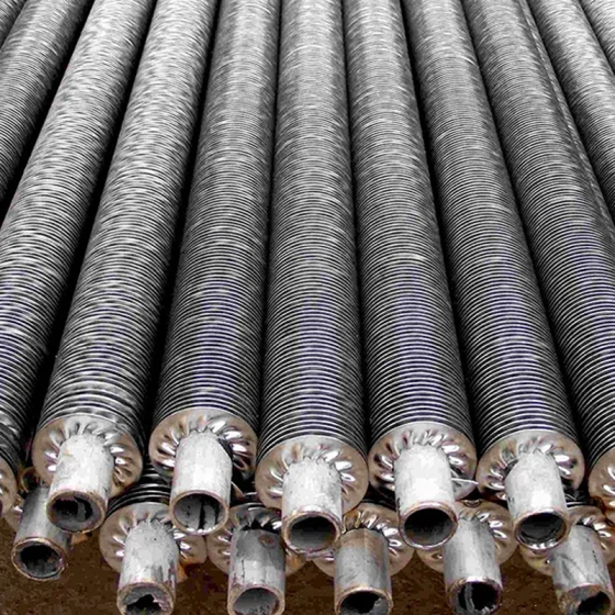
Fin Tube Structure
Finned tubes are the primary heat exchange element in an air cooler, and their structure directly determines the performance of the entire heat exchanger. The connection method between the fins and the base tube also significantly affects heat transfer. Fins used on steel and stainless steel tubes are primarily made of aluminum, steel, or hot-dip galvanized steel.
● High-Efficiency Heat Exchange Fin Tubes
● L-Type Fin Tubes
Suitable for lower temperature applications. Prefabricated L-shaped aluminum strips are spirally wrapped around the heat exchanger base tube. This process creates a larger contact area between the strips and the base tube, allowing heat to transfer from the base tube surface to the fins. This larger contact area improves heat exchange efficiency. This low-cost option is suitable for systems operating at temperatures up to 150°C.
● LL-Type Finned Tube
Aluminum strip is wound to form a double L-shape at the base of the base tube. The fin roots of this finned tube overlap, ensuring better contact with the tube wall and complete coverage. This improves corrosion resistance and allows for an operating temperature range up to 200°C. It is also suitable for wet air coolers; however, the processing difficulty and price are also higher.
● KL-Type Knurled Finned Tube
This is an improvement on the L-shaped finned tube. During manufacturing, the base tube surface is first knurled. During the winding process, the fins are then knurled again, leaving a portion of the L-shaped root embedded in the base tube surface. This results in higher heat transfer efficiency and corrosion resistance, and an operating temperature range of up to 250°C.
● G-Type Embedded Fin Tubes
This process involves pre-forming equally spaced grooves on the base tube surface, installing the fins, and then rolling the groove edges. This creates a secure connection between the fins and the base tube, resulting in high heat transfer efficiency and virtually no impact from high temperatures and external forces. However, its drawbacks include poor corrosion resistance and a relatively low cost.
● DR-Type Fin Tubes
An aluminum tube is sheathed over a base tube and mechanically rolled to secure it. This manufacturing process provides excellent corrosion resistance, high heat transfer efficiency, high fin integrity and rigidity, and ease of cleaning with steam and high-pressure water. However, the equipment cost is high and aluminum consumption increases.
Tube Bundles
Tube Bundle Model Designation
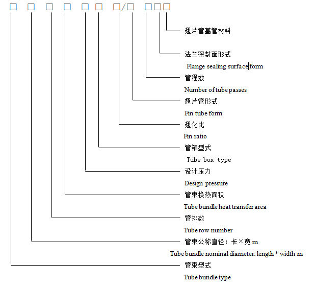
See the table for tube bundle types and codes
| Tube Bundle Type | Code | Tube Box Type | Code | Flange Sealing Surface | Code | Finned Tube Type | Code |
|---|---|---|---|---|---|---|---|
| Blowing Horizontal Tube Bundle | GP | Plug-type Tube Bundle | S | Raised Face Flange | RF | L-Type Finned Tube | L |
| Slant-top Tube Bundle | X | Removable Cover Plate Box | K1 | Tongue (Groove) Face | M (FM) | Double L-Type Finned Tube | LL |
| Induced Horizontal Tube Bundle | YP | Removable Bonnet Box | K2 | Tongue (Groove) Face | T (G) | Knurled Finned Tube | KL |
| Wet Vertical Tube Bundle | SL | Header-type Tube Box | J | Ring Joint Face | RJ | Bimetallic Rolled Finned Tube | DR |
| Dry-Wet Combined Slant Bundle | SX | Lens Gasket Flange | TJ | Embedded Finned Tube | G |
a. Blast-type horizontal tube bundle: 9m long, 2m wide; 6 rows of tubes; base tube heat exchange area 140m²; design pressure 4MPa; removable cover plate tube box; bimetallic rolled fin tubes, fin ratio 23.4; VI tube pass; concave and convex sealing surface of the connecting flange; material 09Cr2AlMoRE; tube bundle model: GP9×2-6-140-4.0K1-23.4/DR-VIMFMD
b. Induced draft horizontal tube bundle: 9m long, 3m wide; 6 rows of tubes; base tube heat exchange area 193m²; design pressure 2.5MPa; plug-in tube box; L-shaped finned tubes, fin ratio 23.4; II tube pass; flange sealing surface with ring connection; carbon steel tube bundle model: YP9×3-6-193-2.5S-23.4/L-IIRJ.
Frame
Frame model designation

Fin Fan Cooler Marking Example
a. Horizontal frame of a forced draft air cooler, 9m long and 4m wide; 2 fans, 3000mm diameter, square box-type; closed frame model: GJP9×4B-30/2F.
Fin Fan Cooler Models and Codes
| Framework Type | Code | Framework Open/Close | Code | Windbox Model | Code |
|---|---|---|---|---|---|
| Blowing Horizontal Framework | GJP | Open Framework | K | Square Box Type | F |
| Slant-top Framework | JX | Closed Framework | B | Transition Cone | Z |
| Induced Horizontal Framework | YJP | Ramp Type | P | ||
| Wet Framework | JS | ||||
| Dry-Wet Combined Framework | JL |
Fin Fan Cooler
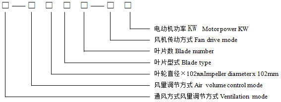
Fin Fan Cooler Model Designation
Marking Example
a. Forced-draft fan, manual angle adjustment when shut down; 2400mm diameter, B-type fiberglass blades, 4 blades; suspended motor with upward-facing V-belt drive, 18.5kW motor power; Model: G-TF24B4-Vs18.5
b. Induced-draft fan, automatic angle adjustment; 3000mm diameter, R-type fiberglass blades, 6 blades; suspended motor with upward-facing V-belt drive, 15kW motor power; Model: Y-2FJ30R6-Vs15
Type and Code
| Ventilation Type | Code | Airflow Regulation | Code | Blade Type | Code | Fan Drive Type | Code |
|---|---|---|---|---|---|---|---|
| Blowing Type | G | Stop-Machine Manual Angle Adjust | TF | R-Type FRP Blade | R | V-Belt Drive | V |
| Induced Type | Y | Non-Stop Manual Angle Adjust | BF | B-Type FRP Blade | B | Direct Motor Drive | Z |
| Automatic Angle Adjust | ZFJ | W-Type FRP Blade | W | Suspended V-Belt Drive (Motor Up) | Vs | ||
| Automatic Speed Adjust | ZFS | Cast Aluminum Blade | L | Suspended V-Belt Drive (Motor Down) | Vx |
Blinds
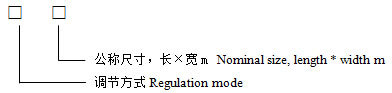
Blind Model Designation
Marking Example
a. Manually adjustable louver, 9m long, 3m wide, model SC9×3
b. Automatically adjustable louver, 6m long, 2m wide, model ZC6×2
Sprinkler System
Sprinkler System Model Notation
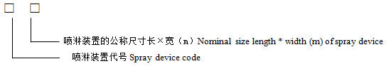
Marking Example: A sprinkler system is 9 meters long and 3 meters wide, and its model number is P9×3
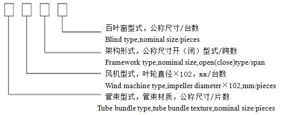
How to indicate the model number of an air cooler
Marking Example
A. Forced Draft Air Cooler: Horizontal tube bundle, 12m x 3m length, 4 tubes, 6 manual fans with 3600mm diameter for manual adjustment during shutdown, horizontal frame. 12m x 6m length, 1-span open frame, 4 manual louvers. Air cooler models for 12m x 3m length are:
GP12×3/4-TF36/5-GJP12×6B/1 GJP12×6K/1-SC12×3/4
B. Induced Draft Air Cooler: Horizontal tube bundle, 12m x 3m length, 2 tubes, 2 manual fans with 3600mm diameter for manual adjustment during shutdown, 1 automatic speed control fan with 3600mm diameter. Horizontal frame, 12m x 6m length. Two air coolers with a single-span closed frame and manually adjustable louvers, measuring 12m long x 3m wide, are available. Models are:
YP12×3/2-TF36/3-ZFS36/1-GJP12×6B/1-SC12×3/2
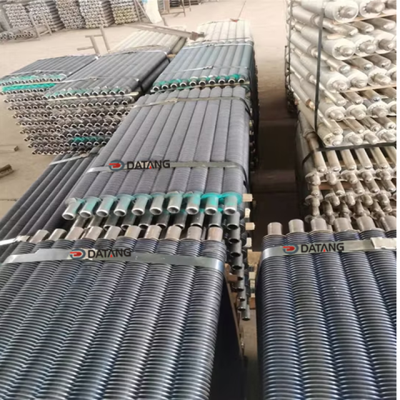
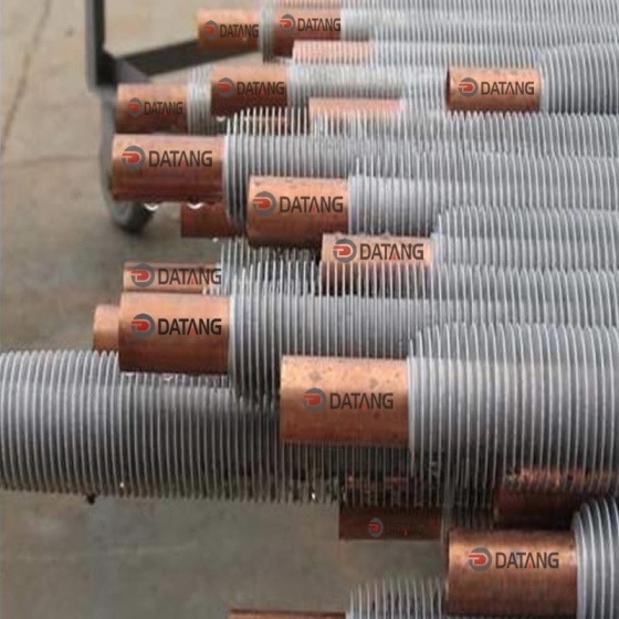
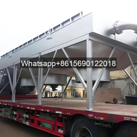
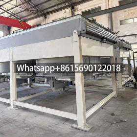
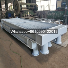
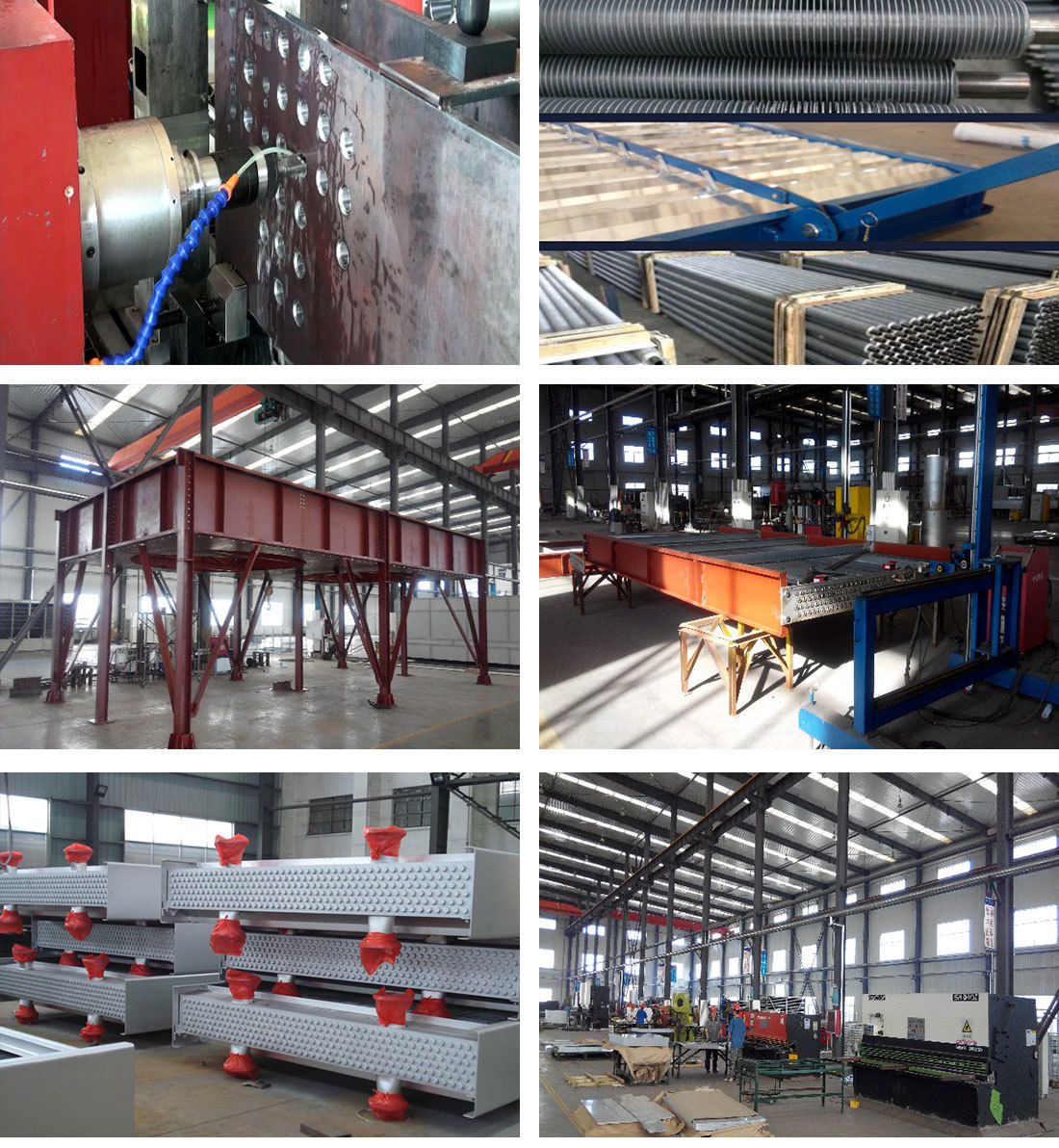
Some product photos


")