Working Principle of Luftvorwärmer in Power Plant Boilers
Power Station Plant Boiler Air Preheater Core Function
The air preheater in a power plant boiler is a heat exchange device installed in the boiler’s rear flue. It recovers waste heat from flue gas to preheat combustion air, improving combustion efficiency and reducing exhaust gas temperature. This achieves an overall energy-saving rate of 5%-10%.
Power Station Plant Boiler Air Preheater Working Mechanism
-
Heat Exchange Process
- Flue Gas Side Heat Transfer: High-temperature flue gas (300–400°C) discharged from the boiler flows through the flue gas channel of the air preheater. Heat is transferred to the surface of metal heat exchange elements (e.g., regenerative plates or tube walls).
- Air Side Heat Absorption: Cold air enters the preheater through the air channel, absorbing heat stored in the elements. Its temperature rises to 200–350°C before being fed into the burner.
- Cyclic Operation: In rotary air preheaters, regenerative elements rotate with the rotor, alternately passing through flue gas and air channels for continuous heat exchange.
-
Key Technical Parameters
- Exhaust Gas Temperature: Reduced from >400°C to 120–200°C via the preheater;
- Combustion Efficiency: Every 50°C increase in preheated air temperature boosts boiler efficiency by approximately 2%–3%.
Power Station Plant Boiler Air Preheater Critical Components and Structure
| Component | Beschreibung |
|---|---|
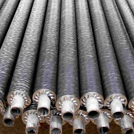
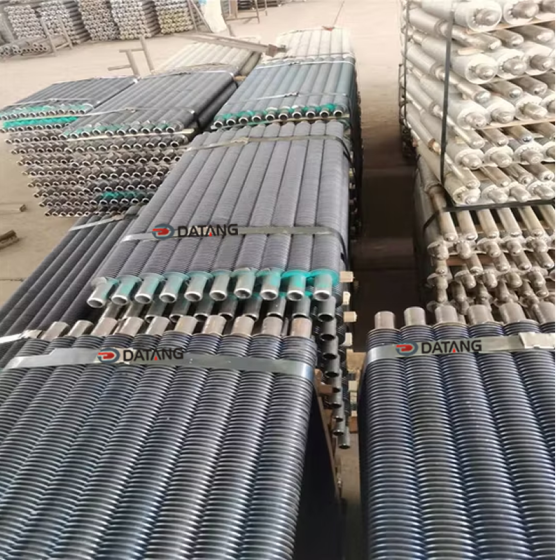
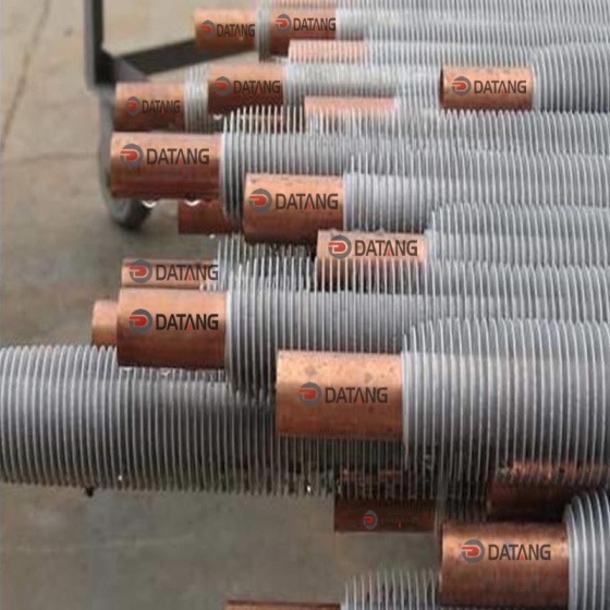
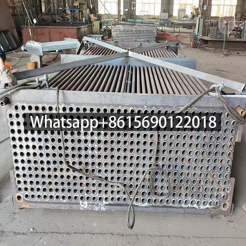
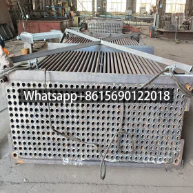
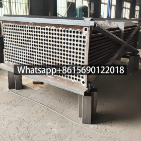
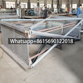
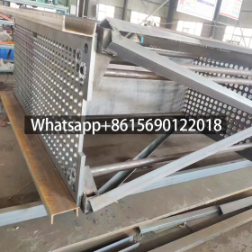
| Heat Storage Elements | Corrugated metal plates or tube bundles designed to maximize heat transfer area (e.g., plates in rotary types, steel tube arrays in tubular types) |
| Rotor & Housing | In rotary designs, the rotor carries heat storage elements and is driven by a motor. The housing separates flue gas/air channels with seals to prevent cross-leakage |
| Sealing System | Radial/axial sealing plates minimize flue gas and air leakage (air leakage rate <8%) |
Power Station Plant Boiler Air Preheater Types and Comparisons
-
Recuperative Type (Tubular/Plate)
- Prinzip: Static conductive heat transfer through metal walls isolating flue gas and air;
- Features: Simple structure, low maintenance, but lower efficiency (suited for small boilers).
-
Regenerative Type (Rotary)
- Prinzip: Cyclic heat storage via periodic contact of elements with flue gas and air;
- Features: High efficiency (>85%), compact size, but complex structure requiring seal maintenance.
Power Station Plant Boiler Air PreheaterPerformance Benefits
- Energy Efficiency: Reduces fuel consumption by 10%–15% and improves overall boiler efficiency by 3%–8%;
- Emission Reduction: Lower exhaust temperatures decrease SOx and NOx formation;
- Combustion Optimization: Preheated air stabilizes fuel ignition, reducing unburned carbon loss.
Power Station Plant Boiler Air Preheater
Boiler Air Preheater Failure and Solution
The role of the air preheater in the boiler is to use the heat of the flue gas at the tail of the boiler to preheat the air required for fuel combustion, thereby improving the operating efficiency of the boiler. It transfers the heat of the flue gas at the tail of the boiler to the air before entering the boiler through the internal heat sink, so that the air reaches a predetermined temperature, thereby improving the heat exchange performance of the boiler and reducing energy consumption.
Air preheaters are widely used in coal-fired power plant boilers. There are various types, including tube box type and rotary type, among which the rotary type can be divided into wind hood rotary type and heating surface rotary type. At present, heating surface rotary preheaters are more common in power plant boilers.
According to different application scenarios, air preheaters can be divided into two-compartment, three-compartment and four-compartment types, and the four-compartment design has been widely used in circulating fluidized bed boilers.
The heat pipe air preheater is a device that uses the heat of the flue gas at the boiler outlet to preheat the boiler combustion air or other drying purposes through the efficient heat transfer of the heat pipe.
Overview of air preheater equipment problems
Wear of air preheater will directly affect the operating efficiency of the boiler. The air preheater involved is a 29–V1 three-compartment rotary type, with a normal speed of 2 rpm, equipped with a 1:12 taper shaft and a minor diameter of 238mm. After testing, the wear of the shaft diameter on one side is about 15mm, and the wear width reaches 140mm. At the same time, the fastening sleeve that matches the sleeve has also worn, and the thrust bearing can no longer be used normally.
Analysis of the causes of air preheater problems
Long-term high-temperature use of the preheater causes deformation and wear. The above wear problems are mainly attributed to the slight deformation of the preheater under long-term high-temperature conditions.
Due to the large weight of the preheater itself, long-term use will cause the bottom beam to sink slightly, which will cause the rotor to tilt and the main shaft to sink. The upper bearing is fixed on the truss to prevent the main shaft from sinking, which causes the gland bolts to be pulled off, and then a gap is generated between the guide end shaft and the fastening sleeve, and they rotate against each other, eventually causing different degrees of wear on both.
Most of the production equipment parts are made of metal materials, which are strong and hard. The vibration impact and composite force during operation can easily lead to a “hard-to-hard” friction relationship between metal parts. After long-term operation, some impact deformation may be converted into permanent deformation, resulting in reduced recovery stress, which in turn causes wear of parts with lower hardness. However, metal materials have poor yieldability. If not discovered and measures are not taken in time, the wear problem will continue to worsen.
Discussion on air preheater solutions
It is necessary to keep the preheater stable, reduce wear and check regularly.
1. Ensure that the preheater remains stable in a high temperature environment to avoid slight deformation.
2. Check the settlement of the bottom beam regularly and adjust the position of the rotor and the main shaft in time.
3. The fixation of the upper bearing and the truss should be strengthened to prevent the main shaft from sinking, thereby preventing the gland bolts from being pulled off.
4. It is also necessary to pay attention to the change in the gap between the guide end shaft and the fastening sleeve, take measures to reduce mutual friction and rotation, and delay the wear process.
5. For the “hard-to-hard” friction between metal parts, the impact force and composite force can be reduced by optimizing material selection and process flow, reducing the risk of permanent deformation and hardness reduction.
6. Regularly check the wear and tear, detect it in time and take corresponding measures to ensure the stable operation of production equipment.