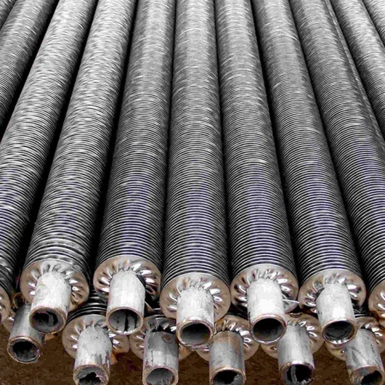


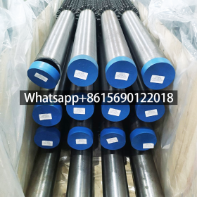
The studded fin tube is a device for enhancing heat transfer. It increases the heat dissipation area by welding cylindrical studs (i.e. fins) on the surface of the base tube, thereby improving the heat exchange efficiency.
Studded Finned Tube Specifications
| Feature | Spezifikation |
|---|---|
| Material der Röhre | All Kinds of Material Can Be Applied |
| Material der Lamellen | Aluminium, Edelstahl, Kupfer, Special metals As Required |
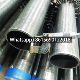
| Rohr-AD (Mm) | 38 – 219 |
| Tube Thickness (Mm) | 4.0 – 15.0 |
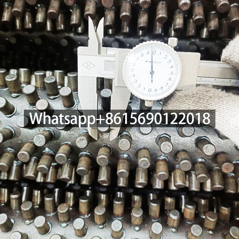
| Stud OD (Mm) | 6 – 16 |
| Stud Height (Mm) | 10 – 45 |
Notes on the table:
- OD: Stands for Outer Diameter.
- Thk: Stands for Thickness.
- Stud: Refers to the pin/stud welded onto the tube base.
- All dimensions (OD, Thk, Stud OD, Stud Height) are in millimeters (Mm).
- The dash (
–) indicates the range of available sizes for each dimension.
Structural features of studded fin tubes
It consists of a base tube (usually a seamless steel tube) and a cylindrical stud, which are welded and fixed by special equipment. The studs are arranged in a square or hexagonal shape. Compared with traditional pin-shaped tubes, a one-time forming process is adopted to avoid the problem of welding pins falling off.
Application scenarios of studded fin tubes
It is mainly used in the convection section of heating furnaces and is suitable for heat transfer scenarios of media such as high-viscosity oil products and heavy oil. It has a compact structure and a high heat transfer coefficient, which can significantly reduce the exhaust temperature and improve the thermal efficiency of the equipment.
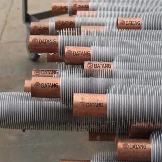
Material and process of studded fin tubes
Base tube: Commonly used carbon steel material, chromium-containing stainless steel or high-temperature resistant alloy material can be selected according to the working temperature.
Welding process: Use an automatic welding machine to firmly weld the nail head to the surface of the base pipe to ensure heat transfer efficiency and structural strength.
Here is the professional manufacturers of the technical specifications for studded fin tubes in corrosive and fouling environments:
️ Ich. Core Structural Optimizations
-
Anti-Fouling Spiral Fin Design
- Non-Uniform Pitch Arrangement: 30°-45° alternating helix angles reduce dust accumulation by 60% while enhancing airflow turbulence.
- Thickened Fins: Fin thickness of 0.3-0.5mm (vs. standard 0.1-0.3mm) improves structural integrity against abrasive particle impact.
- Wide Spacing: Fin pitch expanded to 8-12mm (vs. conventional 2-6mm), balancing heat transfer and cleanability.
-
Composite Base Tube Materials
- Duplex Stainless Steel Tubes: Superior chloride resistance vs. 304 stainless, ideal for sour gas (H₂S >100ppm).
- Kohlenstoffstahl + Lining: Internal epoxy coating (≥200μm) protects against acidic media.
️ II. Corrosion Protection Technologies
-
Surface Treatments
- Enhanced Hot-Dip Galvanizing: 80-120μm zinc layer forms dense ZnO film, passing >5000hr salt spray tests (2× standard).
- Al-Mg Alloy Coating: Replaces galvanizing for high-temp (>200°C) corrosion resistance, stable up to 300°C without zinc volatilization.
-
Weld Joint Protection
- Laser Seam Welding: Eliminates crevices via metallurgical bonding, preventing crevice corrosion.
- Post-Weld Passivation: Nitric acid treatment rebuilds Cr₂O₃ passive film on stainless welds.
? III. Performance Comparison & Selection Guide
| Parameter | Corrosive Environment | Fouling Gas Stream |
|---|---|---|
| Material des Basisrohrs | Duplex Stainless Steel | Kohlenstoffstahl + Epoxy Lining |
| Fin Type | Serrated Fins (enhanced turbulence) | Wide-Pitch Spiral Fins (8-12Mm) |
| Surface Treatment | Al-Mg Alloy Coating | Hot-Dip Galvanizing (120μm) |
| Max. Temperature | 300°C | 250°C |
| Cleaning Interval | 12 months (self-cleaning) | 6 months (manual cleaning) |
? IV. Industrial Case Studies
- Sour Gas Waste Heat Recovery (Petrochemical)
- Duplex SS studded fin tubes operated at 4MPa/280°C in FCC units for 3 years with zero corrosion leaks.
- Biomass Boiler Flue Gas Treatment
- Galvanized carbon steel tubes (10mm pitch) maintained >90% heat transfer efficiency after 18 months despite ash fouling.
? V. Installation & Maintenance Protocols
- Corrosion Prevention During Installation
- PTFE gaskets for flange connections to prevent galvanic corrosion.
- Insulating ceramic spacers between supports/tubes to block stray currents.
- Fouling Environment Maintenance
- Quarterly compressed air back-blowing (0.4-0.6MPa).
- Annual chemical cleaning (5% citric acid circulation).
? Summary
Optimal studded fin tube selection for corrosive/fouling environments requires:
① Material Priority: Duplex SS/alloy coatings for chemical resistance.
② Adaptive Geometry: Wide-pitch non-uniform fins to mitigate fouling.
③ Process Reinforcement: Laser seam welding + thick coatings for longevity.
Recommended for petrochemical/biomass applications with ≥10-year service life potential via regular maintenance.