Copper Low Finned Tubes: Technical Overview with Parameter Tables
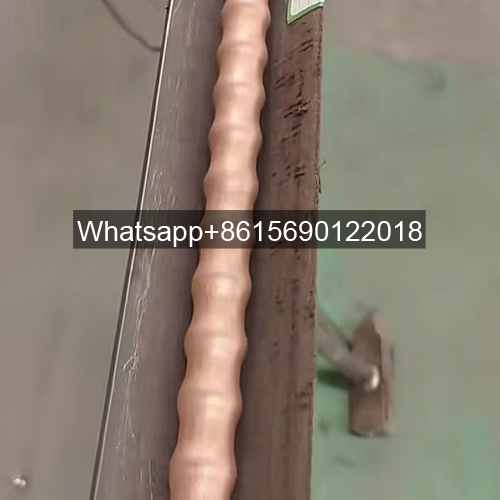
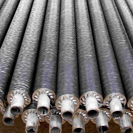
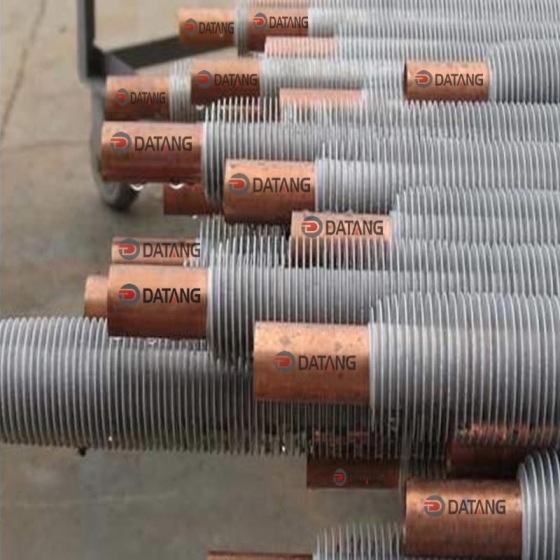
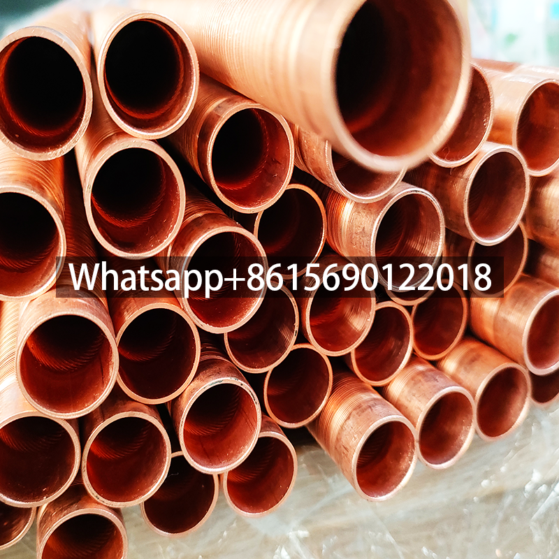
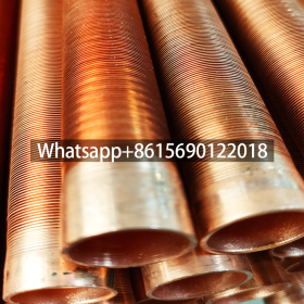
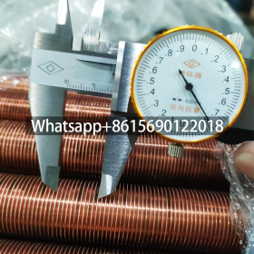
Integral extruded copper low fin tube also called integral low fin tubings are specialized heat exchange components fabricated by mechanically forming continuous spiral fins on plain copper tubes to enhance surface area and thermal efficiency. These tubes are widely employed across industries due to their superior heat transfer properties and durability in demanding environments.
Integral Low Fin Tubing Key Applications
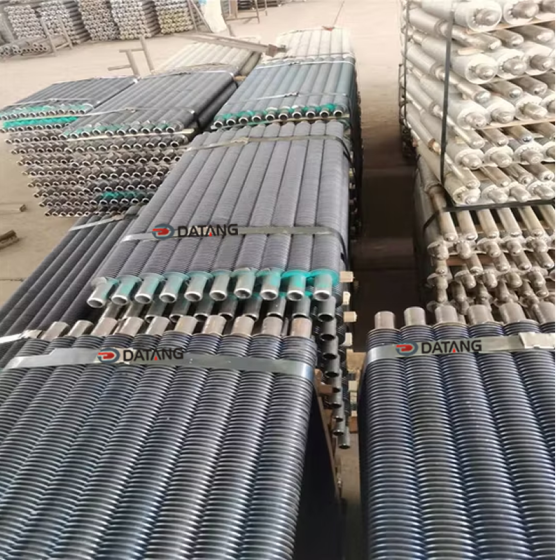
Low fin copper tubes are integral to air conditioning condensers and evaporators, refrigeration systems, oil coolers, and various heat exchangers in power plants, marine applications, and the chemical industry. They also serve critical roles in gas turbine assemblies, diesel cooling units, and waste heat recovery systems.
Integral Low Fin Tubing Performance Parameters and Specifications
Performance is characterized by metrics like the finned ratio (β, the ratio of total external finned surface area to plain tube surface area) and fin efficiency (η), which optimize heat conduction and convection.23 For copper variants, key structural parameters include fin height, fin count per inch (FPI), and dimensional tolerances, typically adhering to standards such as GB/T19447 or equivalent ASTM/ASME specifications.7 Below is a summary of common parameters for copper low finned tubes derived from industry data.
| Parameter | Value Range/Common Values | Unit | Remarks |
|---|---|---|---|
| Material | Copper T2/TP2, Brass HSn70-1 | – | Also includes iron white copper BFe10-1-1 |
| Plain End Outer Diameter | Φ12 to Φ25.4 | mm | Corresponds to imperial sizes (e.g., 1/2″ to 1″) |
| Wall Thickness | 1.0 to 1.5 | mm | Applies to the tube body |
| Fin Height | ≤1.45 | mm | Maximum dimension for efficiency |
| Fins Per Inch (FPI) | 19 to 50 | fins/inch | Higher FPI increases surface area |
| Root Diameter | 12.7 to 19.05 | mm | Based on plain tube dimensions |
| Total Length | ≤8 | m | Standard production limit |
| Fin Thickness | Refer to wall thickness specs | mm | Often derived from initial tube wall |
These parameters ensure optimal thermal performance and mechanical integrity, with customization available for specific industrial requirements. Copper’s excellent corrosion resistance and conductivity make these tubes ideal for high-efficiency heat exchange applications globally.