
An air-cooled heat exchanger is a device that exchanges heat through air convection, and mainly relies on external air flow to achieve heat dissipation. The following are its core points:
Working Principle of Air-Cooled Heat Exchanger
Through the plate-fin heat exchange structure, the high-temperature medium (such as flue gas or refrigerant) and the cold air are forced to exchange heat through convection, transferring heat to the air and achieving cooling. For example, in the flue gas treatment system of the incinerator, the high-temperature flue gas above 800℃ can be reduced to below 200℃.
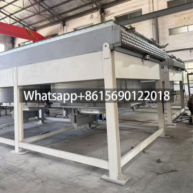
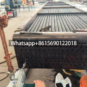
Structural Composition of Air-Cooled Heat Exchanger
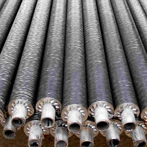
It usually includes three core components: manifold, gas channel and wind channel. The plate-fin structure improves the heat dissipation efficiency by increasing the heat exchange area, and the fin design further enhances the thermal conductivity.
Application Scenarios of Air-Cooled Heat Exchanger
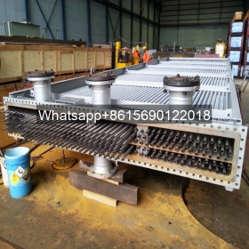
It is widely used in the field of industrial heat dissipation, such as flue gas treatment, refrigeration system (such as air-cooled heat pump unit), etc. In the air-cooled heat pump unit, it replaces the water cooling system and completes the refrigerant heat transfer through air circulation. It has the advantages of easy installation and no need for additional water source.
Here is the professional of the comprehensive analysis and implementation plan for air-cooled heat exchanger solutions:
? I. Core Working Principles & Structural Design
-
Heat Exchange Mechanism
- Forced Convection Cooling: Fans drive airflow across fin-tube bundles, facilitating heat transfer between the internal hot fluid (water/oil) and air. Heat passes through tube walls to fins and is dissipated by airflow16.
- High-Efficiency Materials: Aluminum or copper fins (thermal conductivity >4000 W/(m·K)) with expanded surface areas (e.g., corrugated designs) enhance thermal efficiency.
- Heat-Pipe Assistance: Low-boiling-point fluid evaporates/condenses within sealed heat pipes, rapidly transferring heat to remote fins to eliminate local hotspots.
-
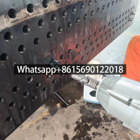
Critical Component Design
- Fin Structure: High-density staggered fins increase airflow turbulence, expanding effective heat transfer area by 30% vs. flat fins56; Hydrophobic/hydrophilic coatings prevent moisture accumulation.
- Airflow Optimization: Dual-side intake or 3D duct designs minimize dead zones; paired with high-airflow fans (≥2500 m³/h per kW) for uniform cooling.
- Pressure Resistance: Brazing + TIG welding ensures structural integrity; Aluminum plate-fin coolers operate at ≤2.5 MPa to withstand hydraulic shock.
? II. Key Performance Enhancement Technologies
-
Dynamic Temperature Control & Efficiency Optimization
- Variable Frequency Drive (VFD): Compressor/fan speed adjusts dynamically to loads, reducing partial-load energy consumption by >20%.
- Smart PID Algorithms: Real-time temperature differential monitoring enables ±0.1°C precision (-40°C to ambient).
- Hybrid Dual-Engine Design: Pre-cooler modules + free-cooling utilization (e.g., fluorine pump systems switch to natural cooling in low temperatures, reducing compressor load).
-
Maintenance & Reliability Improvements
- Anti-Dust Design: Bottom airflow intake with dust collection hoppers; quarterly high-pressure water fin cleaning prevents clogging and efficiency loss.
- Corrosion-Resistant Materials: 1Cr18Ni9Ti stainless steel or titanium tubes (Cl⁻ resistance >300 ppm) for corrosive industrial environments.
? III. Scenario Adaptation & Selection Strategy
| Application Scenario | Recommended Solution | Advantages |
|---|---|---|
| Low-Medium Power Cooling | Aluminum plate-fin + heat pipe hybrid | Compact structure, low maintenance (≈2% CAPEX/year) |
| High-Density Data Centers | Air-liquid hybrid cooling (≤130kW/rack) | Liquid precision + air flexibility, PUE≤1. |
| High-Temp Industrial | Full-VFD air-cooled units + hydrophobic fins | Tolerates >35°C ambient, ΔT≤4°C |
| Hydraulic System Cooling | High-pressure plate-fin coolers (≥16 bar) | Resists hydraulic shock, oil ΔT≥180°C |
️ IV. Implementation Considerations
- Space & Installation: Maintain ventilation clearance (≥1.5× device width) to prevent hot air recirculation; Drain fluids in subzero environments to avoid freeze damage.
- Cost Trade-offs:
- Air Cooling: Lower CAPEX, but efficiency lags liquid cooling at high power;
- Liquid Cooling: Optimal for sustained high-load operations, requires water treatment.
- Efficiency Certification: Prioritize Grade-1 energy-efficient equipment with smart controls (e.g., Sacon Cloud platforms) for energy visibility.
Conclusion: Air-cooling suits medium/low-power, space-restricted, or water-scarce scenarios; high-density/high-heat scenarios demand air-liquid hybrid architectures. Final selection must balance thermal load, environmental tolerance, lifecycle cost, and maximize efficiency through intelligent controls.


")