
Spiral Helical Crimped Finned Tubes for Heat Exchangers
I. What is a Crimped Fin Tube?
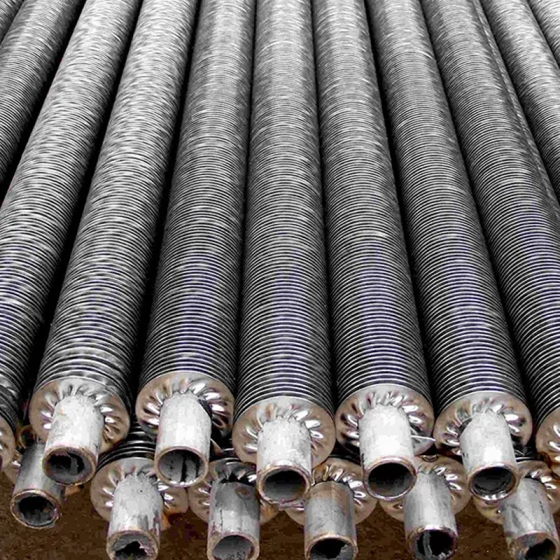
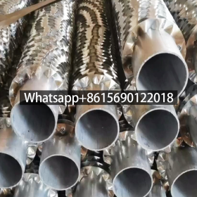
A crimped fin tube is a heat transfer enhancement component in finned-tube heat exchangers. Its defining feature lies in the cold-forming process (room-temperature winding) that fixes metal fins onto the base tube surface, creating an external fin structure. This design is particularly suited for scenarios where one side (typically the external medium) has a low heat transfer coefficient.
Crimped Fin Tubes Specifications
Key Parameters of Crimped Fin Tubes
| Parameter Category | Specification Range/Description | Notes |
|---|---|---|
| Nominal Diameter (DN) | DN25, DN32–42mm (non-standard custom), DN65, 4″/1.5″/2.5″ | Adapts to diverse scenarios; supports non-standard customization12 |
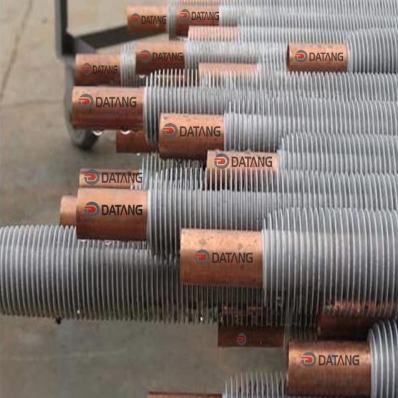
| Base Tube Material | Carbon steel, stainless steel, alloy steel | Stainless steel excels in corrosion resistance; carbon steel requires galvanization24 |
| Fin Height | 10–20mm | Controls finned ratio to enhance heat dissipation area8 |
| Fin Spacing | 1.5–10mm | Small spacing (1.5–2.5mm) for high-density heat exchange; large spacing for low-resistance applications8 |
| Fin Thickness | 0.5–0.8mm (metal) | Optimizes thermal conductivity and structural strength balance8 |
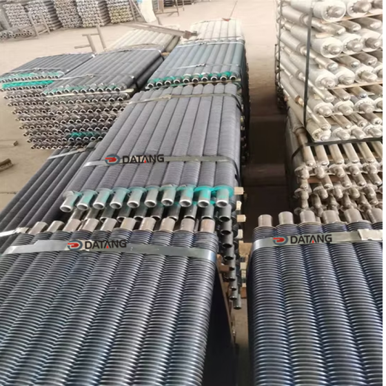
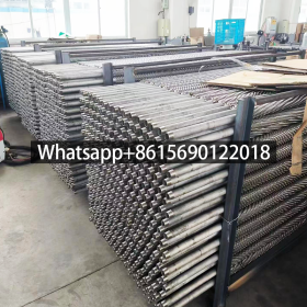
| Length Range | 1–6m (standard), supports extended customization | Reduces on-site splicing joints through tailored cutting3 |
| Pressure Rating | ≤2.5MPa (standard) | Special reinforcement required for high-pressure scenarios16 |
| Operating Temperature | -50°C to 300°C | Suitable for both low-temperature heating and medium/high-temperature industrial uses6 |
| Anti-Corrosion Treatment | Hot-dip galvanizing (≥80μm coating), anti-corrosion paint | Prolongs lifespan in corrosive environments (e.g., chemical plants, marine settings)27 |
| Installation Methods | Flanged connection, threaded interface, modular straight-tube splicing | Flanges ensure high-pressure sealing; modular designs simplify construction13 |
Critical Parameter Details
Fin Configuration Design
- Fin Shapes: Flat, corrugated, or slotted fins to optimize fluid turbulence and heat transfer efficiency8
- Arrangement: Staggered or aligned patterns affect airflow distribution and thermal uniformity8
Non-Standard Customization
- Adjustable fin height, spacing, and base tube wall thickness for extreme conditions (e.g., explosion-proof, high-dust environments)8
- Specialized fin designs (e.g., spiral-wound, annular fins) enhance turbulent flow effects8
Notes:
- All specifications comply with pressure pipeline component standards and material adaptability requirements12.
- Non-standard options are validated through mechanical and thermal performance testing37.
II. Working Principles of Spiral Wound Finned Tubes
Spiral wound finned tubes are enhanced heat transfer elements that combine fins with base tubes via mechanical cold-working. Their core principle involves increasing heat transfer area and optimizing thermal conduction paths to improve heat transfer efficiency on one side (usually the external medium). Below is a detailed breakdown:
1. Crimped Finned Tube Mechanical Interlocking for Heat Transfer Interface Formation
Cold-Forming Process
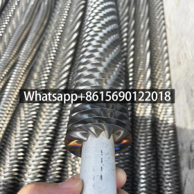
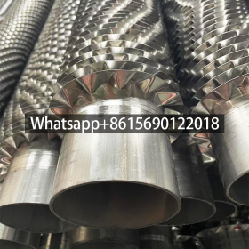
- At room temperature, specialized equipment (e.g., fin winding machines) applies radial pressure and circumferential tension to spiral-wrap metal strips onto base tubes (e.g., stainless steel, carbon steel tubes).
- Through plastic deformation, the fin roots tightly bond with the base tube surface, forming a mechanical interlock (similar to a “press-fit” structure) without welding. Contact pressure can reach 50–100 MPa.
Bonding Mechanism
- Mechanical Preload: Residual stress from winding ensures long-term interface stability, minimizing gaps caused by thermal expansion/contraction.
- Micro-Asperity Interlocking: Microscopic roughness on the base tube and fin surfaces interlocks, reducing contact thermal resistance (typical values ≤0.01 m²·K/W).
2. Crimped Fin Tube Extended Heat Transfer Area
Fin Geometric Design
- Fin height (5–25 mm), spacing (3–10 mm), and arrangement (spiral or annular) directly affect heat transfer area.
- Effective heat transfer area reaches 3–5 times that of bare tubes (for the same base tube length).
Optimized Thermal Conduction Path
- Heat flows from the base tube wall through the fin roots (contact interface) to the fin surface, then dissipates via convection/radiation.
- Fin material thermal conductivity (e.g., aluminum: 237 W/(m·K), copper: 401 W/(m·K)) is critical for efficiency.
3. Crimped Fin Tube Avoiding Thermal Defects
Advantages of Cold Processing
- Traditional welding or hot rolling may alter material properties (e.g., carbon steel oxidation, aluminum softening) due to high temperatures.
- No heating in cold winding preserves original mechanical properties (hardness, tensile strength, etc.).
Microstructural Integrity
- Base tube and fin metallurgical structures remain unaffected, making them suitable for material-sensitive applications (e.g., food-grade stainless steel to prevent intergranular corrosion).
4. Spiral Crimped Finned Tube Heat Transfer Formula
The thermal efficiency of cold-wound finned tubes can be quantified by:
�=ℎ⋅�eff⋅Δ�
- �: Heat transfer rate (W)
- ℎ: Overall heat transfer coefficient (W/(m²·K)), incorporating fin efficiency correction
- �eff: Effective heat transfer area (m²)
- Δ�: Temperature difference between media (K)
Fin Efficiency (�): Ratio of actual heat transfer to ideal heat transfer, determined by fin conductivity, geometry, and convective conditions.
5. Crimped Fin Tube Thermodynamic Balance in Applications
- Low-Temperature Difference Adaptation: Expanded surface area compensates for small temperature gradients (e.g., effective operation in waste heat recovery with Δ�≤30∘C).
- Self-Cleaning Property: Spiral fin structures induce turbulent airflow, reducing dust accumulation (lowering maintenance frequency by 20–40%).
IV. Stainless steel Crimped Fin Tube Application Areas
Stainless steel crimped fin tubes are widely utilized across industries due to their high heat transfer efficiency, corrosion resistance, and process flexibility. Key application domains include:
1. Spiral Crimped Finned Tube for Heat Exchanger Power Industry
- Thermal Power Generation:
- Deployed in boiler economizers and air preheaters, increasing coal combustion efficiency by expanding heat exchange area and reducing exhaust gas temperature (typical cases show over 5% thermal efficiency improvement).
- Nuclear Power Plants:
- Used in reactor cooling systems for stability under extreme conditions, leveraging high corrosion resistance.
- Electrical Equipment Cooling:
- Provides heat dissipation for transformers, generators, and other equipment to prevent overheating-induced failures.
2. Crimped Fin Tube Chemical Industry
- Reactor Temperature Control:
- Regulates chemical reaction temperatures to avoid thermal runaway or suboptimal conditions.
- Raw Material Storage:
- Maintains stable temperatures during storage/transport of thermally sensitive chemicals to prevent degradation.
3. Crimped Fin Tube Renewable Energy
- Solar Thermal Collectors:
- Enhances heat collection efficiency in solar thermal conversion systems.
- Wind Turbine Cooling:
- Supports heat dissipation in wind turbine generators for prolonged operational stability.
4. Crimped Fin Tube Industrial Heating & HVAC Systems
- Centralized Heating:
- Core component of radiators, accelerating heat transfer from hot water to air (e.g., northern China’s heating systems).
- Industrial Air Conditioning:
- Balances equipment-generated heat with ambient temperatures in factory workshops.
5. Crimped Fin Tube Metallurgy & Manufacturing
- High-Temperature Equipment Cooling:
- Cools smelting furnaces, rolling mills, and other equipment to prevent metal deformation.
- Process Fluid Cooling:
- Regulates temperatures for industrial cooling water, oils, and other media.
6. Spiral Crimped Fin Tube Waste Heat Recovery & Environmental Protection
- Flue Gas Heat Recovery:
- Extracts waste heat from coal-fired boiler exhaust, reducing energy consumption (e.g., ≥15% fuel cost reduction in some cases).
- Industrial Exhaust Treatment:
- Recovers waste heat in emission control systems to lower carbon footprints.
Key Advantages Highlighted:
- Corrosion Resistance: Ensures durability in harsh environments (e.g., chemical exposure, high humidity).
- Modular Design: Adaptable to diverse geometries and operating conditions.
- Energy Savings: Directly reduces operational costs through efficient heat recovery and transfer.